Protection of Transformers at
Offshore Substation Platforms (OSP)
OHVS and HVDC
In modern society, a lot of offshore substation technology is used 24/7. Even to the level that we have grown to be totally dependent on electrical power, as well as in our private lives as in most commercial or industrial activities.
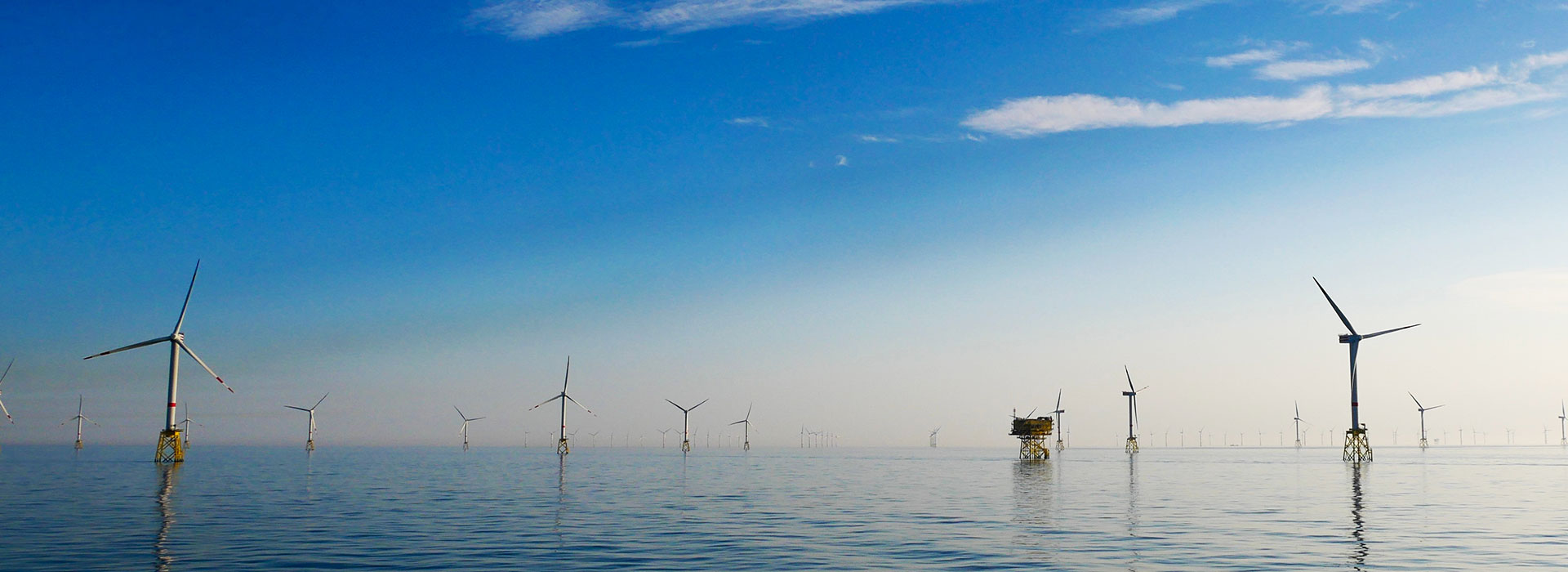
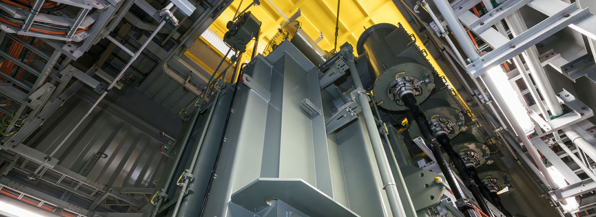
The renewable electric power industry has installed offshore substations in their distribution grids to accommodate the ever increasing demand for dependable power with their rows of large high voltage power transformers. Many precautions have been taken to safeguard them against failure. Because when all power fails, customers complain, revenues are lost and even medical emergencies can happen.
One of the risks these large transformers have is fire. Although the manufacturers of these oil filled transformers build them with diverse imbedded safety features, if they fail they often produce very large fires that are very hard to extinguish and provoke environmental damages with the release of thick black toxic smoke and spilling of transformer oil.
This is why energy companies install fire protection systems at offshore substation to protect their investment and to prevent such fires.
Our staff is fully VCA, GWO, BOSIET, FOET and HUET trained for commissioning, maintenance and support.
Problems
with the use of traditional technologies
Most oil cooled high voltage power transformers have a deluge sprinkler system. Designers use NFPA-15 as a guide to design a system that will cool off the transformer and eventually, extinguish the fire.
A typical design calls for a grid of open type deluge or spray nozzles to be installed all around the transformer. Such a system will use a minimum 44 nozzles and will be designed to spray at least 1,900 L/min of water for the duration of one (1) hour. That is a lot of water!
NFPA-850 for Power Plant Design goes even further, requesting water spray duration to last a full two (2) hours! But demands for sump tanks are specified to be large enough to contain the spill and the fire water from the fire suppression systems. So the size of the sump tanks is too big, the weight is too heavy and the costs are too high.
Prevent
High Opex costs
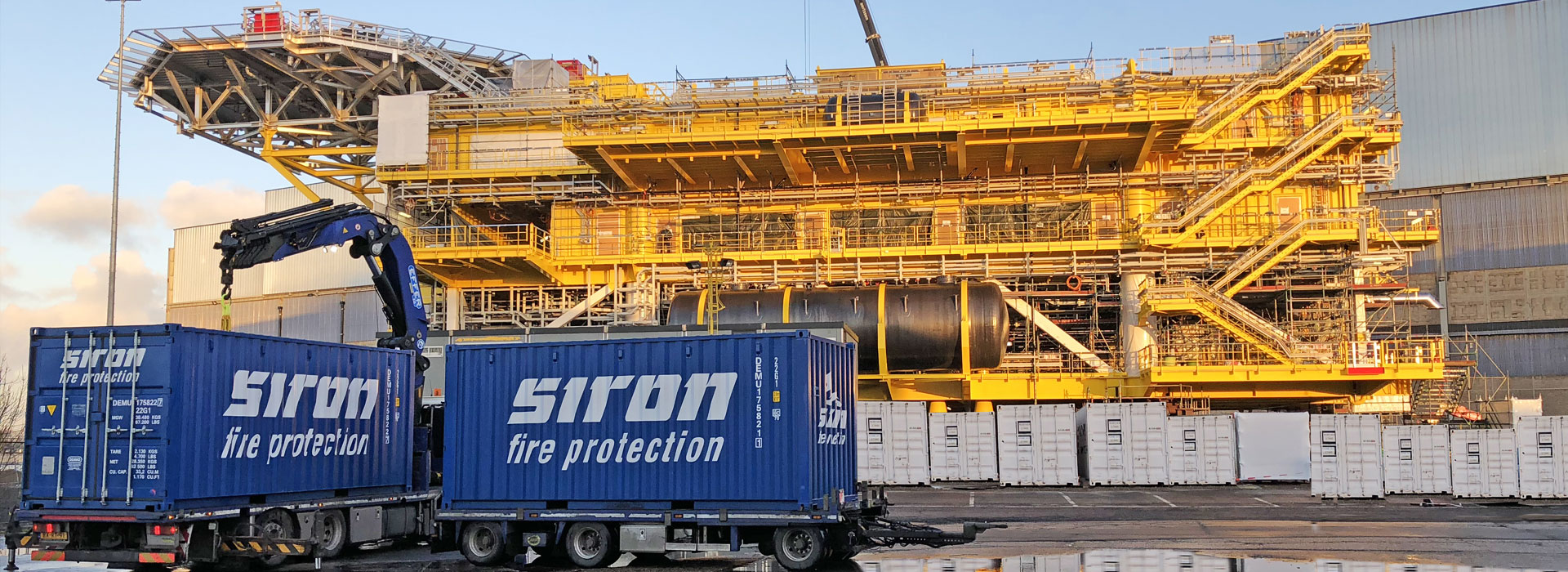
Offshore Substation Platforms (OSP) OHVS and HVDC are mostly unmanned and should preferably not have (sea) water based fire pumps because of the cost to maintain this system. Every 2 weeks these pumps have to be test-operated. In the lifespan of an OSS and OHVS it is assumable that the pump has to be replaced or overhauled two to three times.
Mixing foam with salt water is also a very costly business because of the corroding properties of sea water. A solution to these problems is available using a SIRON’s Integrated Compressed Air Foam system (ICAF).
Please also note that our ICAF system does not work with a premix. Maintenance operations therefore are a lot smaller and will save costs. Premix systems must be replaced every few years, against extremely high costs because the premix tank must be cleaned and the “old” premix must be processed.
The water and foam in SIRON’s ICAF system is not premixed so the quality will stay in good condition for 20-25 years. This combination will reduce maintenance during its entire life span, so SIRON can offer a fixed price for lifetime (20 years) maintenance.
NFPA design
This FM Approved AFFF foam system allows the designer to alleviate many of these potential problems while providing superior fire protection (AFFF stands for Aqueous Film Forming Foam and is a fire fighting foam widely used in the industry to extinguish fires in hydrocarbon fuels such as transformer oil).
NFPA-11 states that where fixed spray type systems are used to protect three-dimensional equipment like power transformers, the minimum density should be applied over the projected area of rectangular prism envelope for the equipment and its appurtenances. Furthermore, system discharge duration should be designed for a minimum period of 5 minutes.
FM approved
Using our FM Approved ICAF Design Manual, the designer (or we can do it for you) will locate a grid of local application nozzles to cover the transformer’s surfaces, based upon the published square area of coverage versus mounting distance ratio of the TAR-225L Nozzles.
But because of the coverage area of each nozzle and the dense texture of Compressed Air Foam, the spray nozzles grid all around the transformer uses a lot less nozzles than the equivalent deluge system.
The quantity of foam concentrate is also reduced by using the ICAF System since its high efficiency is achieved while using only a 2% concentration of AFFF foam concentrate instead of the usual 3%! The above designed oil cooled transformers have been fire tested and approved by FM.
Less water
For a typical transformer such as the one shown in Figures 1 & 2 (see below), ICAF Systems are designed at a much lower water flow rate, for example 360 L/min for a grid of only 16 nozzles. Because of the much shorter discharge time of 5 minutes, the total water quantity will be dramatically reduced; only about 1,800L of water will be needed to completely suppress the fire.
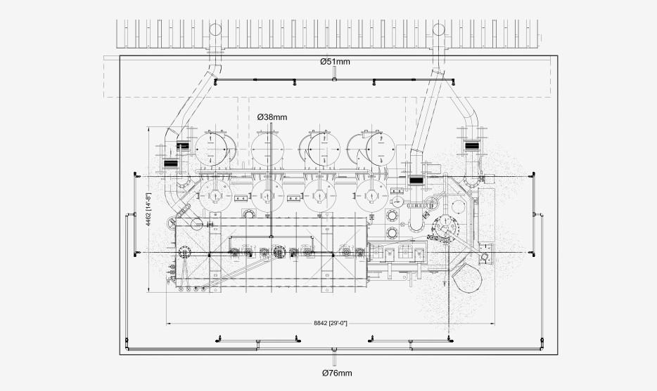
Figure 1
Top view nozzle layout
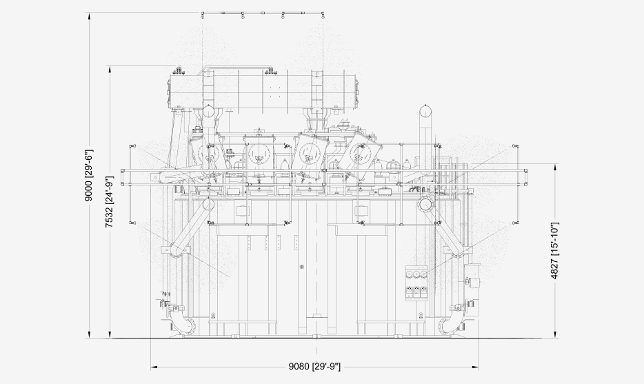
Figure 2
Front view nozzle layout
Less
weight
Immediately, one can see that the need for large sea water pumps and large sump tanks is no longer necessary and large investment savings can be made and maybe more importantly: weight can be reduced. Even with a much more efficient fire protection system protecting the expensive equipment.
No
pollution
After extinguishing, the small quantity of water, foam and transformer oil can easily be pumped and treated. Possible damage to the environment is reduced to a minimum because the risk of overflowing the sump tank with fire water and transformer oil into the sea is eliminated.
Burn-back
resistant
The ICAF System is certified and full fire tested specifically for burning transformers. It provides protection against burn-back for more than 30 minutes, which other systems cannot do.
Difficult
to extinguish
Typically, an oil cooled transformer fire will involve both a cascading fire from the oil coming down from the expansion tank situated at the top of the casing and a pool fire in the curb surrounding the transformer, which makes it very difficult to extinguish.
Transformers Test Video (see below) shows a typical ICAF System installation with its grid of discharge nozzles installed around the transformer. A first row of nozzles will be aimed at the top of the transformer casing to extinguish flames from the pooling transformer oil on its top.
A second row will be installed as shown to protect the sides of the transformer casing, extinguishing the cascading fire. Foam accumulation in the curb will handle the burning oil by covering the surface. Other nozzles (as shown) will be located to properly cover the shape of the oil expansion tank.
